

How To Set Up Inter Vlan Routing
past Darin Knobbe on Nov 18, 2022 ix:09:59 AM
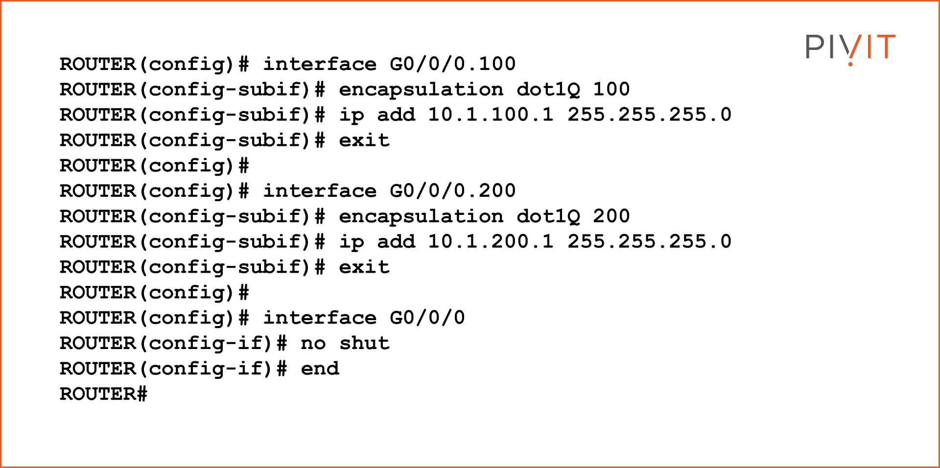
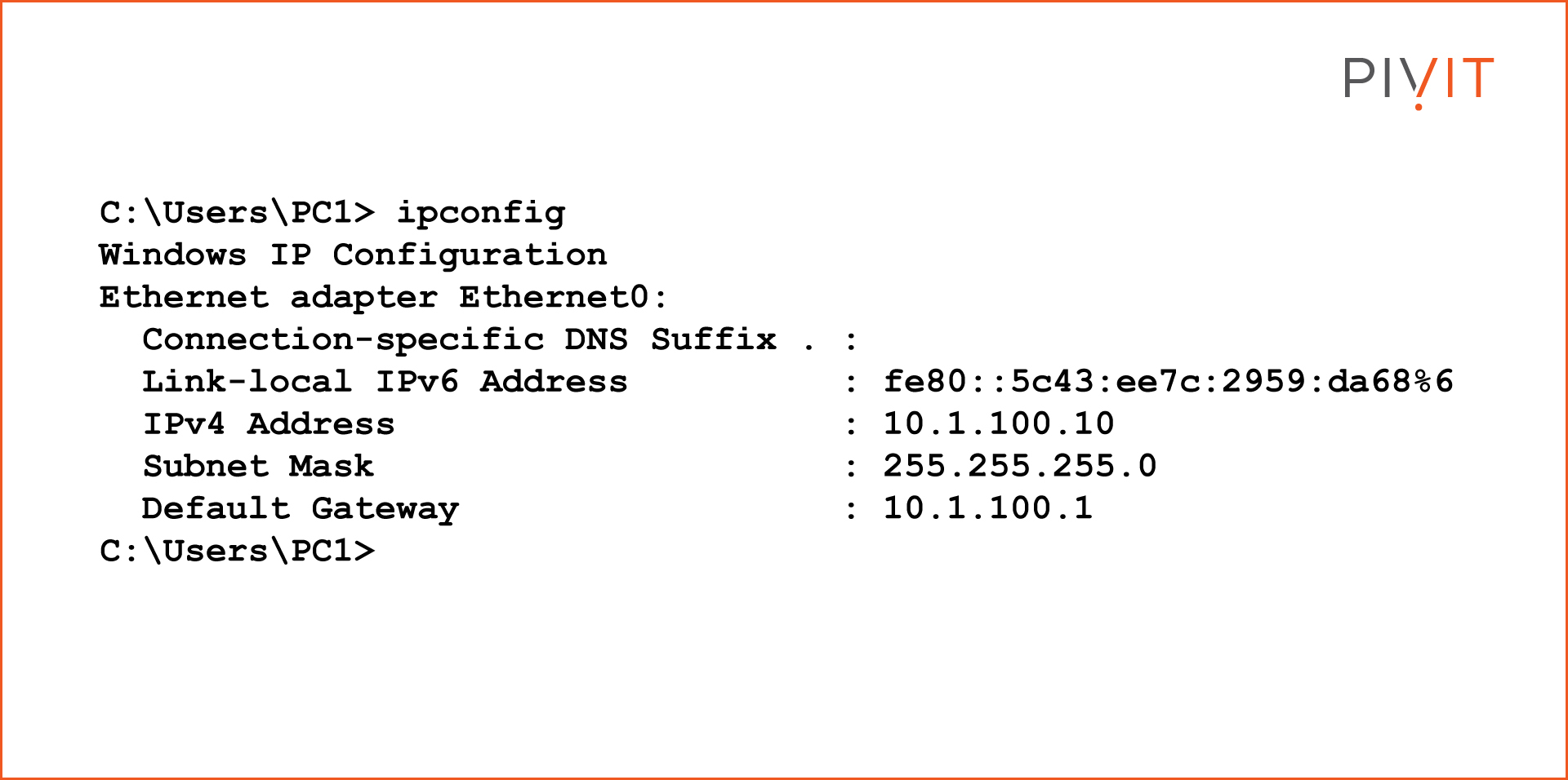
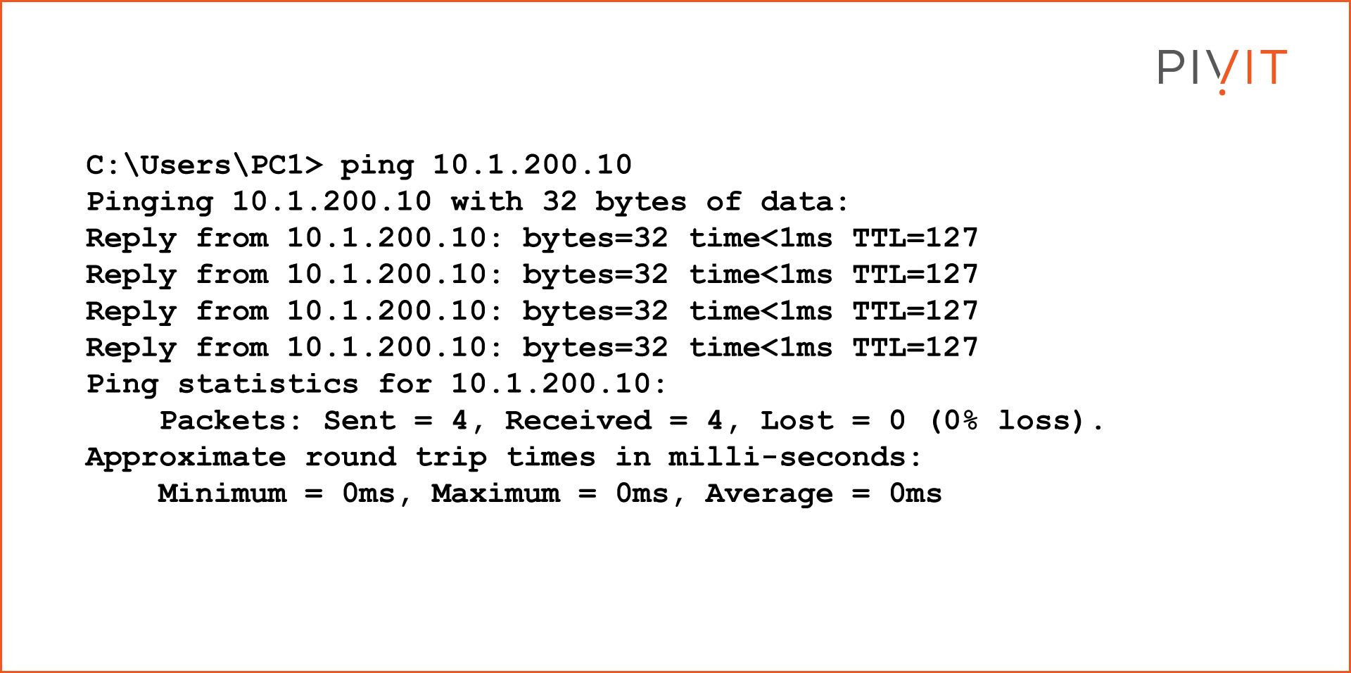
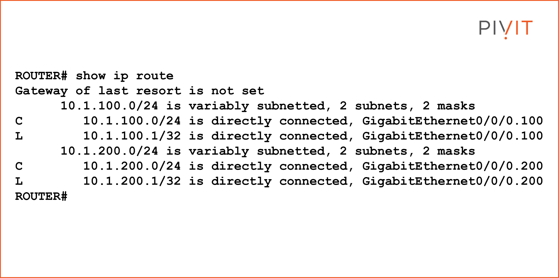
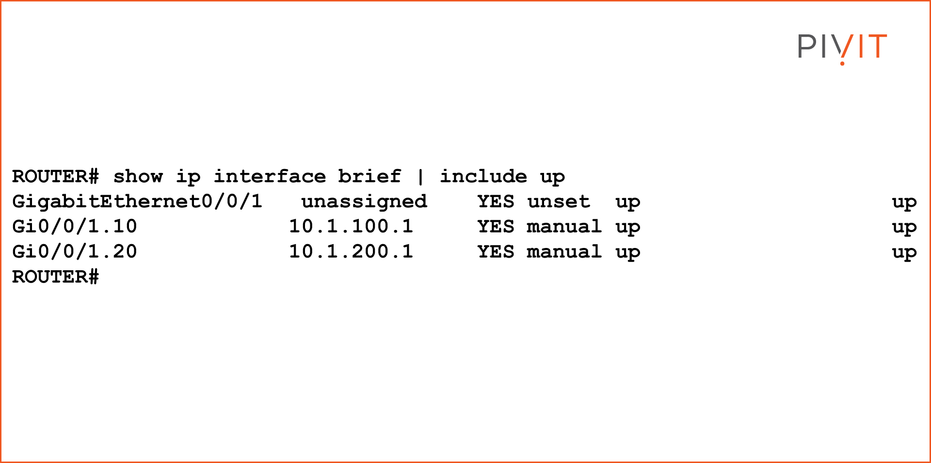
In a Layer 2 switched environment, VLANs separate devices into unlike standoff domains and Layer 3 subnets. Devices in the same VLAN tin communicate without any routing, and devices in different VLANs require routing to communicate with each other. L2 switches require an L3 routing device to communicate between different VLANs, and the device is either an external router or Layer iii module on the same chassis. Nigh of the Cisco switches have routing capabilities within the switch. When the switch receives a packet, it determines that it belongs to another VLAN, and the switch sends the packet to the appropriate port on the other VLAN. This web log volition talk over inter-VLAN routing configuration examples in Cisco routers and switches. VLANs are used to segment Layer 2 networks. Hosts from one VLAN cannot communicate with hosts in another VLAN unless a router or a Layer 3 switch provides routing services. Inter-VLAN routing is the applied science for communication network traffic from one VLAN to another VLAN. There are ii well known inter-VLAN routing options: The "router-on-a-stick" inter-VLAN routing technique needs only 1 concrete interface to route traffic among multiple VLANs on a network. A router's concrete interface is configured as an 802.1Q torso and continued to the Layer 2 switch's body interface. The router interface is configured using subinterfaces for passing multiple VLANs in one interface. The configured subinterfaces are software-based virtual interfaces, and each subinterface is associated with a single physical Ethernet interface. Each sub-interface is configured for different subnets that correspond to their VLAN assignment, which facilitates logical routing. When VLAN-tagged traffic enters the router interface, the traffic is forwarded to the VLAN subinterface according to the VLAN tag ID. Afterward a routing decision is performed based on the destination address, the router determines the egress interface for the traffic. NOTE: The router-on-a-stick inter-VLAN method does not scale beyond 50 VLANs. This section describes how to configure the router-on-a-stick inter-VLAN routing method. You tin see in the image beneath that the router is connected with a switch using a single interface, and can pass multiple VLANs using that interface via a router-on-a-stick inter-VLAN routing configuration. The router GigabitEthernet 0/0/0 interface is connected to the Layer 2 switch Ethernet 1/1 port. The Ethernet i/1 is a trunk link that is required to forward traffic within and betwixt VLANs. To road betwixt VLANs, the Router GigabitEthernet 0/0/0 interface is logically divided into ii subinterfaces, as shown in the table below. The tabular array also shows the two VLANs that volition exist configured on the switch. G0/0/0.100 100 x.ane.100.one/24 G0/0/0.200 200 10.one.200.1/24 Assume that the Router and Switch take basic configurations. Currently, PC1 and PC2 cannot ping each other because they are on different networks. To enable the PCs to communicate, we need to configure VLANs and trunking in the switch level, and the router must be configured for inter-VLAN routing. Complete the following steps to configure Switch with VLANs and trunking: For each VLAN, you lot demand to create a subinterface in the router-on-a-stick method. A subinterface tin be created using the interface_id.subinterface_id format in the global configuration fashion. The subinterface syntax is the physical interface followed by a period and a subinterface number. Although non required, information technology is common to match the subinterface number with the VLAN number. Afterwards creating the subinterface, enable the interface with the "no shutdown" command in the interface configuration mode. All the subinterfaces are disabled if the physical interface is disabled. In the below configuration, the Router G0/0/0 subinterfaces are configured for VLANs 100 and 200. After the switch trunk and the router subinterface configurations, the router-on-a-stick configuration is complete. The configuration can be verified from the PC, router, and switch. From PC1, verify connectivity to a host in another VLAN using the ping command. The output confirms the IPv4 address and default gateway of PC1. Next, use ping to verify connectivity with PC2, every bit shown in the below output. The ping reply confirms that inter-VLAN routing is working. Use the below testify commands to verify and troubleshoot the router-on-a-stick configuration. Every bit shown in the below output, verify that the subinterfaces appear in the router's routing table by using the "show ip route" command. Detect that there are two continued routes (C) and their corresponding exit interfaces for each routable VLAN. The output confirms that the subnets, VLANs, and subinterfaces are active. Some other useful router command is to show the ip interface brief, every bit shown below. The output confirms that the subinterfaces take the right IPv4 address configured and that they are operational. Subinterfaces can be verified using the show interfaces subinterface-command, equally shown in the below output. Inter-VLAN Routing
Router-on-a-Stick Inter-VLAN Routing Method With a Cisco Router
Router-on-a-Stick Inter-VLAN Routing Configuration Example
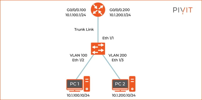
Subinterface VLAN IP Accost VLAN and Trunking Configuration in Switch
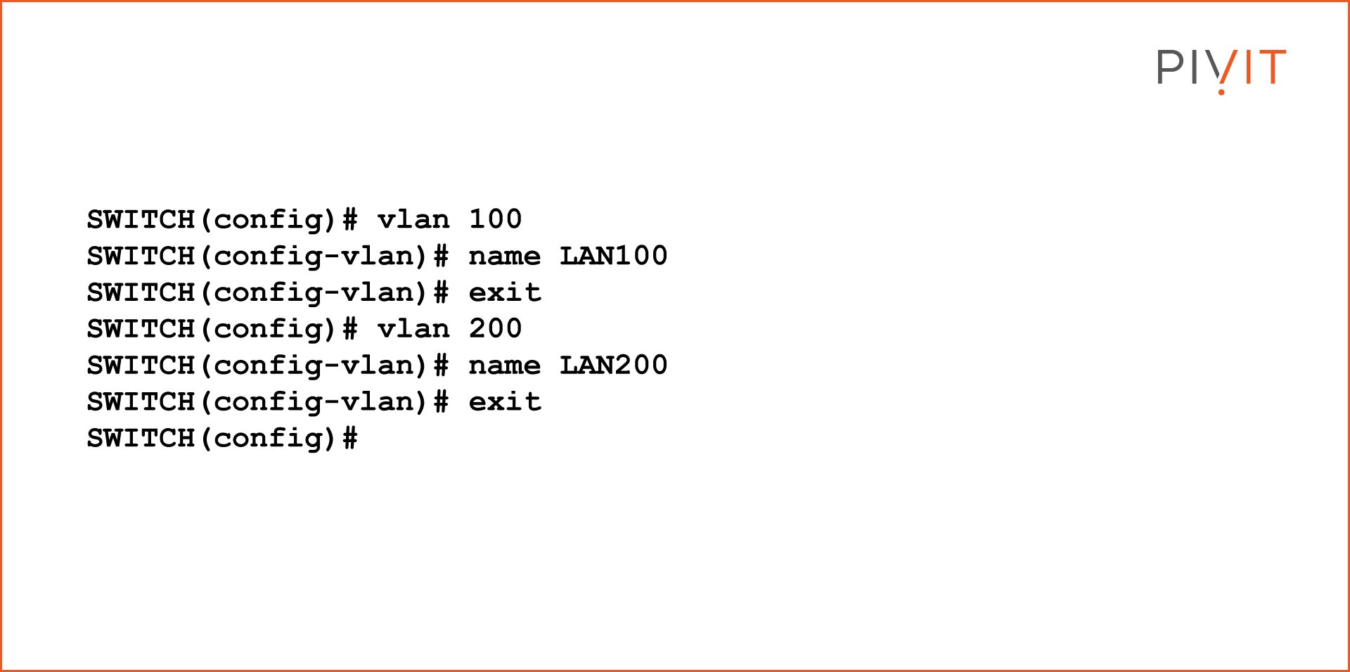
VLAN Configuration
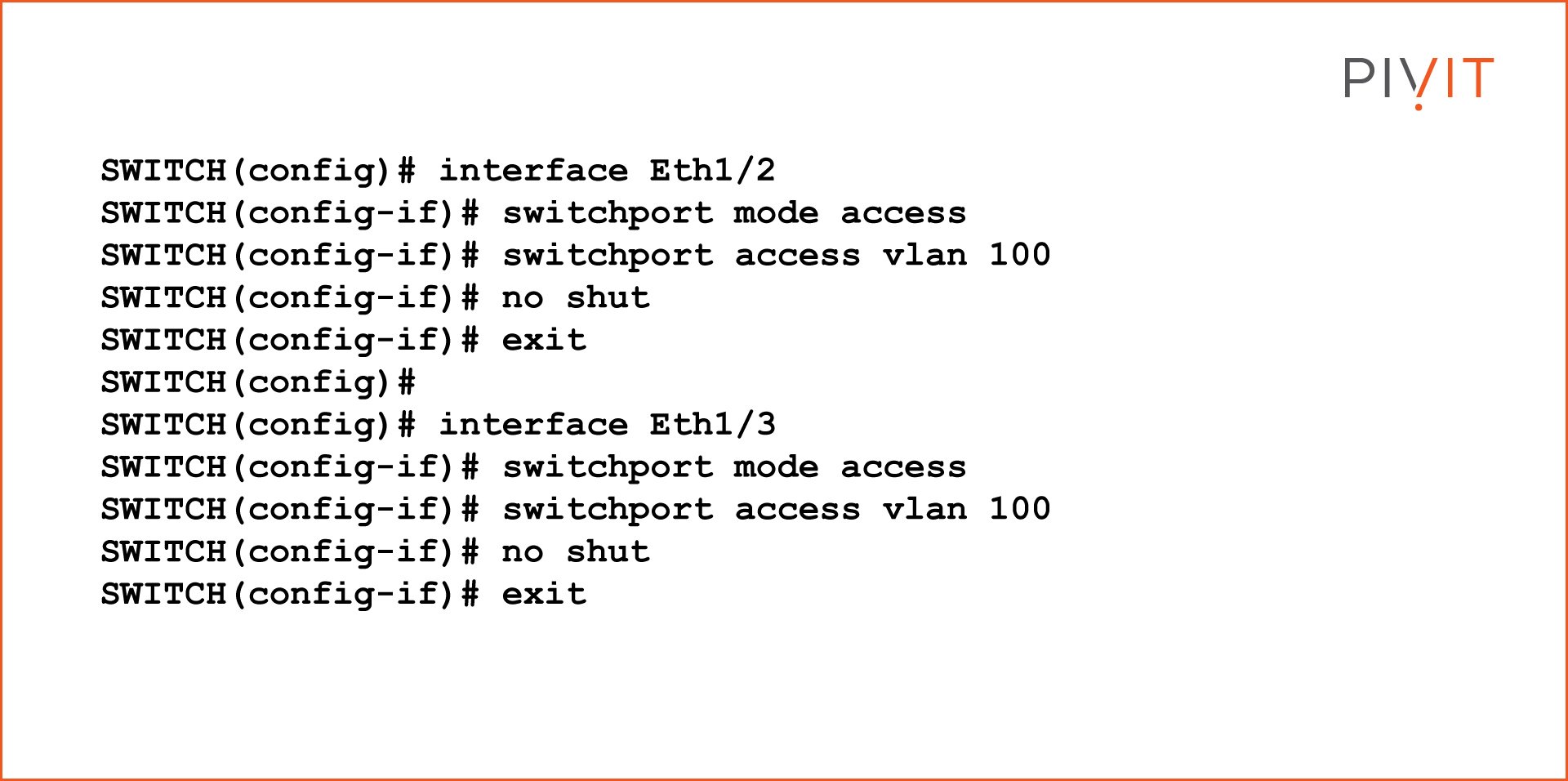
Access Port Configuration
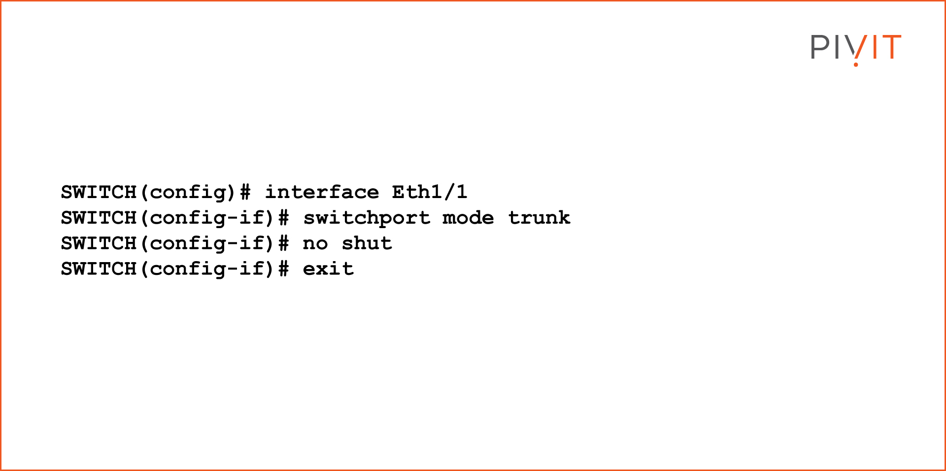
Trunking Port Configuration
Router Subinterface Configuration
Verify Connectivity Between PC1 and PC2
Windows PC IP Accost
Router-on-a-Stick Inter-VLAN Routing Verification


How To Set Up Inter Vlan Routing,
Source: https://info.pivitglobal.com/resources/inter-vlan-routing-configuration-guide-for-cisco
Posted by: osheamiturie.blogspot.com
0 Response to "How To Set Up Inter Vlan Routing"
Post a Comment